LACP overview
Link Aggregation Control Protocol
Within the IEEE specification the Link Aggregation Control Protocol (LACP) provides a method to control the bundling of several physical ports together to form a single logical channel. LACP allows a network device to negotiate an automatic bundling of links by sending LACP packets to the peer (directly connected device that also implements LACP).
Advantage over static configuration
Failover when a link fails and there is (for example) a Media Converter between the devices which means that the peer will not see the link down. With static link aggregation the peer would continue sending traffic down the link causing it to be lost.
The device can confirm that the configuration at the other end can handle link aggregation. With Static link aggregation a cabling or configuration mistake could go undetected and cause undesirable network behavior.
Practical notes
LACP works by sending frames (LACPDUs) down all links that have the protocol enabled. If it finds a device on the other end of the link that also has LACP enabled, it will also independently send frames along the same links enabling the two units to detect multiple links between themselves and then combine them into a single logical link. LACP can be configured in one of two modes: active or passive. In active mode it will always send frames along the configured links. In passive mode however, it acts as "speak when spoken to", and therefore can be used as a way of controlling accidental loops (as long as the other device is in active mode).
LACPDU
Frame format
A single message type, the LACPDU, is transmitted by protocol participants. It comprises the following information both for the transmitting actor, and its remote partner: the partner information being the actor’s current view of its partner’s parameters.
· Port Number
· System ID
· Key
· Status
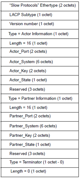
The Status information communicated comprises the following flags:
· LACP_Activity
· LACP_Timeout
· Aggregate
· Synchronization
· Collecting
· Distributing
The LACP_Activity flag indicates a participant’s intent to transmit periodically to detect and maintain aggregates. If set the flag communicates Active LACP, if reset Passive LACP. A passive participant will participate in the protocol if it has an active partner.
The LACP_Timeout flag indicates that the participant wishes to receive frequent periodic transmissions, and will aggressively times out received information. If set the flag communicates Short Timeout, if reset Long Timeout.
The Aggregation flag indicates that the participant will allow the link to be used as part of an aggregate. Otherwise the link is to be used as an individual link, i.e. not aggregated with any other. This flag is set or reset as a consequence of local key management: the participant may know that the link has a unique key9 and hence will not be aggregated. Signaling this information allows the receiving actor to skip protocol delays that are otherwise invoked to allow all links with the same system id and key combinations to be collected into one aggregate port without successive rapid changes to aggregate ports and accompanying higher layer protocol disruption.10 If set the flag communicates Aggregatable, if reset Individual. The Synchronization flag indicates that the transmitting participant’s mux component is in sync with the system id and key information transmitted. This accommodates multiplexing hardware11 that takes time to set up or reconfigure.12 If set the flag communicate In Sync, if reset Out of Sync.
The Collecting flag indicates that the participant’s collector, i.e. the reception component of the mux, is definitely on. If set the flag communicates collecting. The Distributing flag indicates that the participant’s distributor is not definitely off. If reset the flag indicates not distributing.
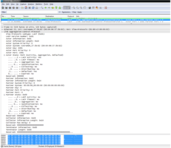
Captured frame
LACP operation
Transmitting LACP PDU
The port must first be added to the Aggregator’s Select-List. Then it will start its Wait-While-Timer while it waits for other links to get ready for aggregation as well.
As soon as all links’ Wait-While-Timers expire, they are set to ATTACHED state in the Mux-Machine, and their Actor.Sync state is set to TRUE. It will advertise this Actor.Sync = TRUE value in its next PDU being transmitted.
When the link receives a PDU indicating that its Partner is also in Sync = TRUE state, the link is ready to be added to the trunk for sending and receiving traffic.
LACP will send a message to Vlan Manager indicating this member port needs to be added to the trunk.
When Vlan Manager receives this message, it will set the member-ports status to FORWARDING, and send a message to HAL indicating ADD member port to trunk.
When HAL process is done with adding the member-port to the trunk, it will send an Acknowledgement (ACK) to Vlan Manager indicating it is done. Vlan Manager forwards this ACK to LACP process.
When LACP Process receives the ACK, it will set its Actor’s Collecting and Distributing values to TRUE, and then transmit a LACP PDU.
How do links aggregate together
Links can aggregate together if they have the same:
Actor System Id, Actor Oper Key, Partner System Id, Partner Oper Key.
In EXOS
- The Actor System Id will be the System MAC address.
- The Actor Oper Key will always be the same as the Admin Key configured for this Lag.
- The Partner System Id will be learnt from received PDU. Or if no pdu is received and Rx_State enters DEFAULTED, then it will be the value configured by user.
- Partner Oper Key will also be learnt from received PDU. Similarly if no pdu is received and Rx_State enters DEFAULTED, then it will be the value configured by user.
While starting off all links have Selected value set to UNSELECTED, and Mux_state value to DETACHED. As PDUs are received, their respective LAG_Ids are created. The smallest Lag_Id amongst all links in each Lag is the one that will be assigned to that Lag’s Aggregator’s Operational-LAG-Id.
So, as new LAG_Ids are formed, they will be compared to their Aggregator’s Operational-LAG-Id. If they match, then the link is valid candidate for being part of the Aggregator. It will be put on the Aggregator’s SELECTED list or STANDBY list depending on the capacity of the Aggregator.
LABTEST with EXOS 15.2
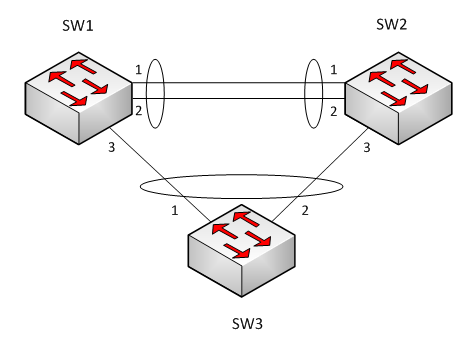
Diagram

HW & SW
HW: BD8800 * 3 EA
SW: ExtremeXOS version 15.2.2.7 v1522b7-patch1-2 has been used.
LACPDU status
- SW3 receive the LACPDU from sw1 and sw2 and the system id of each LACPDU has different system mac address, so port 6:1 and 6:3 are not aggregated on sw3.
[LACPDU from sw1 to sw3]

[LACPDU from sw2 to sw3]
BD-8806.11 # show lacp member-port 6:1
Member Port Rx Sel Mux Actor Partner
Port Priority State Logic State Flags Port
--------------------------------------------------------------------------------
6:1 0 Current Unselected Detached A-G----- 3011
================================================================================
Actor Flags: A-Activity, T-Timeout, G-Aggregation, S-Synchronization
C-Collecting, D-Distributing, F-Defaulted, E-Expired
LABTEST with EXOS 15.3
Diagram
HW & SW
HW: BD8800 * 3 EA
SW: ExtremeXOS version 15.3.0.7 has been used.
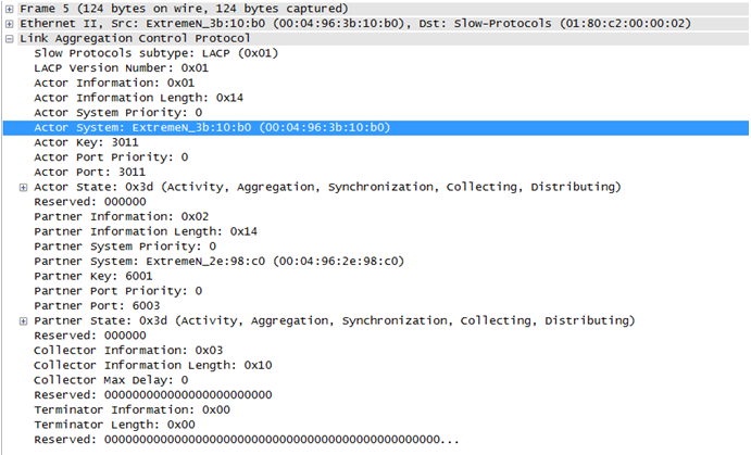
LACPDU status
- Following command is possible on EXOS 15.3 version, and lacp-mac address should be identical between sw1 and sw2.
configure mlag peer "core1" lacp-mac xx:xx:xx:xx:xx:xx
if same lacp-mac configured, then system id of LACPDU from sw1 and sw2 is identical.
[LACPDU from sw1 to sw3]

[LACPDU from sw2 to sw3]

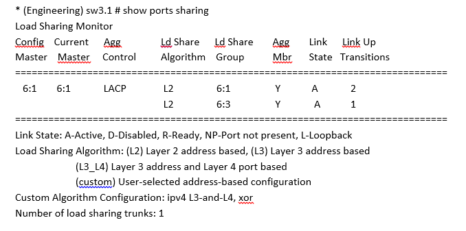
- Port 6:1 and 6:3 are aggregated on sw3.
LACPDU Transmission on MLAG Ports
To prevent the server node from forming two separate aggregators to the MLAG peers (which could result in a loop), it is necessary that both MLAG peers transmit LACPDUs with the same System Identifier and Actor Key. The following points discuss how the System Identifier is determined:
• The MLAG peers must communicate at least once with each other to generate LACPUDs on MLAG ports. If the MLAG peers do not communicate with each other, no LACPDUs are sent out on the MLAG ports. The MLAG peers checkpoint their system MAC and checkpoint the configured MAC to the peer to determine the LACP Operational MAC.
• If no LACP MAC is configured on the MLAG peers, the LACP Operational MAC is the MAC address of the MLAG peer that has the highest IP address for ISC control VLAN.
• If a different LACP MAC address is configured on the MLAG peers, the configured MAC is not used. In this case, the LACP Operational MAC address is the MAC address of the MLAG peer that has the highest IP address for ISC control VLAN.
• The configured MAC address is only used when the same MAC is configured on both the MLAG peers.
Scalability Impact on Load Shared Groups
When static load sharing is used for the MLAG ports, and if there is a single link connecting the server node and the MLAG peer switches, the port does not need to be configured as a load shared port on the MLAG peer switches. Configuring LACP on MLAG ports can reduce the number of load shared ports that can be configured in the system.
Configuration Guidelines
• LACP configuration for MLAG ports (system priority, LACP timeout, activity mode, etc.) should be the same on all the MLAG peer switches.
• We recommend that the server node has a lower System Aggregation Priority than the MLAG peers so that the server node chooses which of the ports can be aggregated. As an example, there are a maximum of 8 ports that can be aggregated together, and there are eight links from Peer1 to the Server, and another eight links from Peer2 to the server node. When the server node has a lower System Aggregation Priority, it can choose which of the total available links can be aggregated together.
• If the Port Aggregation Priority is not configured for the load shared member ports, there is a
chance that only the links from server node to one of the MLAG peer are aggregated together
(based on the port numbers). In this instance, the links from the server node to the other MLAG peer are unused. To avoid this, you can configure the Port Aggregation Priority on the server node so that the number of active links to the MLAG peers is balanced.
• You must configure load sharing groups on all the MLAG ports even if they contain just one port. Below are sample configurations.
Configuration on Peer1
create vlan "isc"
configure vlan isc tag 4000
enable sharing 5 grouping 5,10 lacp
configure vlan "isc" add ports 5 tagged
configure vlan "isc" ipaddress 1.1.1.1/8
create mlag peer "peer2"
configure mlag peer "peer2" ipaddress 1.1.1.2
configure mlag peer "peer2" lacp-mac 00:11:22:33:44:55
enable sharing 6 grouping 6,12 lacp
enable sharing 18 grouping 18 lacp
enable mlag port 6 peer "peer2" id 1
enable mlag port 18 peer "peer2" id 2
Configuration on Peer2
create vlan "isc"
configure vlan isc tag 4000
enable sharing 5 grouping 5,10 lacp
configure vlan "isc" add ports 5 tagged
configure vlan "isc" ipaddress 1.1.1.2/8
create mlag peer "peer1"
configure mlag peer "peer1" ipaddress 1.1.1.1
configure mlag peer "peer1" lacp-mac 00:11:22:33:44:55
enable sharing 20 grouping 20 lacp
enable sharing 6 grouping 6,15 lacp
enable mlag port 20 peer "peer1" id 1
enable mlag port 6 peer "peer1" id 2
Configuration on Server Nodes (assumed to be Extreme Switches)
enable sharing 1 grouping 1,2,3 lacp
configure sharing 1 lacp system-priority 100
configure lacp member-port 1 priority 10
configure lacp member-port 2 priority 20
configure lacp member-port 3 priority 15

No comments:
Post a Comment