1. MLAG
Multi System LAG, or MLAG, is an innovation that builds upon 802.3ad (Link Aggregation Groups – LAG) by allowing a device to aggregate its ports as one logical port while connecting them across two different receivers in a “V” pattern.
MLAG simply adds a multi-path capability to traditional LAG. Each switch communicates with the end-device as one logical entity. The switch “pair” uses an Inter-Switch Connection (ISC) to keep the connection synchronized and occasionally to move data. The ISC is created using directly connected Ethernet links. It is strongly recommend that load sharing be used for the ISC to accommodate sufficient bandwidth for the network traffic.
2.Topology and Configuration
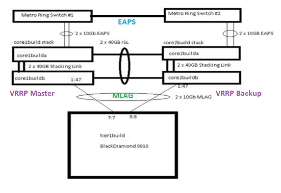
Two core switches are running routing services across VLAN boundaries using VRRP for L3 routing and have EAPS for L2 redundancy. MLAG is configured with an aggregate switch as explained in the topology below.

The MLAG configuration is relatively simple as explained below.
[ Core1build ]
Two core switches are running routing services across VLAN boundaries using VRRP for L3 routing and have EAPS for L2 redundancy. MLAG is configured with an aggregate switch as explained in the topology below.
The MLAG configuration is relatively simple as explained below.
[ Core1build ]
enable sharing 1:53 grouping 1:53, 2:53 algorithm address-based L3_L4
create vlan isc
config isc ipadd 1.1.1.1 / 24
config isc add port 1:53 tagged
create mlag peer "core2build"
configure mlag peer "core2build" ipaddress 1.1.1.2
enable mlag port 1:47 peer "core2build" id 40
[ Core2build ]
enable sharing 1:53 grouping 1:53, 2:53 algorithm address-based L3_L4
create vlan isc
config isc ipadd 1.1.1.2 /24
config isc add port 1:53 tagged
create mlag peer "core1build"
configure mlag peer "core1build" ipaddress 1.1.1.1 vr VR-Default
enable mlag port 1:47 peer "core1build" id 40
[ Tier1build ]
Enable sharing 7:7 grouping 7:7, 8:8 algorithm address-based L2
The MLAG remote node (tier1build) can be a switch or server. The load share with the remote node can be a static LAG or an LACP.
3. MLAG Support over LACP:
Beginning in EXOS 15.3, the EXOS MLAG feature supports Link Aggregation Control Protocol (LACP) over MLAG ports. To do this, all MLAG peer switches use a common MAC in the System Identifier portion of the LACPDU transmitted over the MLAG ports. The following options and requirements are provided:
Beginning in EXOS 15.3, the EXOS MLAG feature supports Link Aggregation Control Protocol (LACP) over MLAG ports. To do this, all MLAG peer switches use a common MAC in the System Identifier portion of the LACPDU transmitted over the MLAG ports. The following options and requirements are provided:
• The MLAG peer that has the highest IP address for the ISC control VLAN is considered the MLAG LACP master. The switch MAC of the MLAG LACP master is used as the System Identifier by all the MLAG peer switches in the LACPDUs transmitted over the MLAG ports. This is the default option.
• You can configure a common unicast MAC address for use on all the MLAG peer switches. This MAC address is used as the System Identifier by all the MLAG peer switches in the LACPDUs transmitted over the MLAG ports. This configuration is not validated between the MLAG peers, and you must make sure that the same MAC address is configured on all the MLAG switches. Additionally, you must ensure that this address does not conflict with the switch MAC of the server node that is teamed with the MLAG peer switches.
MLAG Troubleshooting:
There are two main ‘show’ commands that provide current MLAG peer and port status.
When an ISC link goes down in between the peers, MLAG port and peer status will be seen as shown below;
Slot-1 core1build.8 # show mlag port 1:47
Local Local Remote
MLAG Local Link Remote Peer Fail Fail
Id Port State Link Peer Status Count Count
================================================================================
40 1:47 A N/A core2build Down 0 0
================================================================================
Local Link State: A - Active, D - Disabled, R - Ready, NP - Port not present
Remote Link : Up - One or more links are active on the remote switch,
Down - No links are active on the remote switch,
N/A - The peer has not communicated link state for this MLAG
port
Number of Multi-switch Link Aggregation Groups : 12
Convergence control : Conserve Access Lists
Slot-1 core1build.9 # sh mlag peer
Multi-switch Link Aggregation Peers:
MLAG Peer : core2build
VLAN : isc Virtual Router : VR-Default
Local IP Address : 1.1.1.1 Peer IP Address : 1.1.1.2
MLAG ports : 12 Tx-Interval : 1000 ms
Checkpoint Status : Down Peer Tx-Interval : 1000 ms
Rx-Hellos : 7882543 Tx-Hellos : 7901911
Rx-Checkpoint Msgs: 3892866 Tx-Checkpoint Msgs: 4960040
Rx-Hello Errors : 0 Tx-Hello Errors : 0
Hello Timeouts : 0 Checkpoint Errors : 0
Up Time : N/A Peer Conn.Failures: 0
Local MAC : 02:04:96:6d:17:f7 Peer MAC : 02:04:96:6d:17:e8
Config'd LACP MAC : None Current LACP MAC : 02:04:96:6d:17:e8
The FDB entries learned via ISC link (with ‘S’ flag) will be flushed as well.
* Slot-1 core2build.130 # sh fdb
Mac Vlan Age Flags Port / Virtual Port List
------------------------------------------------------------------------------
00:04:96:6d:6f:4c routing-backbone(2480) 0000 d mi 1:45
>>>>>>>> no FDB entries with ‘S’ Flag <<<<<<<
Flags : d - Dynamic, s - Static, p - Permanent, n - NetLogin, m - MAC, i - IP,
x - IPX, l - lockdown MAC, L - lockdown-timeout MAC, M- Mirror, B - Egress Blackhole,
b - Ingress Blackhole, v - MAC-Based VLAN, P - Private VLAN, T - VLAN translation,
D - drop packet, h - Hardware Aging, o - IEEE 802.1ah Backbone MAC,
S - Software Controlled Deletion, r - MSRP
When dealing with traffic loss over MLAG peers, keeping the above topology in mind, the following list of ‘debug’ commands are recommended to be run (and captured) on the switches and possibly to be shared for further analysis.
i. Identify the affected location and traffic in the network and verify ARP, FDB, and routing entries for the traffic in MLAG peer and remote switch.
a. Show fdb
b. Show iparp
c. Show iproute
d. Debug hal show fdb
ii. Verify if there is either port or CPU congestion and check the IP/L2 statistics for the VLANs across all the three switches. Confirm whether packets are being dropped on the Core1 or Core2 switch.
a. Debug hal show congestion
b. Show port <por#> congestion
c. Show Ipstats
d. Show L2stats
iii. Verify that all the MAC address entries are synced between core switches over the ISC link through “show fdb” output. Additionally collect command output from both MLAG peers for the following;
a. Debug fdb show mlag <mlag port>
b. debug fdb show isc <isc port>
c. debug fdb show vsm vlan isc
d. debug vsm show peer <peer name>
e. debug vsm show ports id <mlag port id>
f. debug vsm show ports peer <peer name>
g. debug vsm show ports ports <portlist>
h. debug hal show vsm
i. debug fdb show globals
Case Study with Real Examples
Example-1: FDB entries are not aging out on MLAG peers after removing hosts from the network. FDB table started growing on both MLAG peers in an environment where 1000+ VMs are added /removed on a daily basis. The associated FDB entries for those VMs are not aging out. There is no apparent traffic issue with the growing table. Though FDB process consumes 30-40% of CPU, stack continues to operate and functions normally. However, there is always the risk for the switch to experience a process crash or an outage.
Abnormal behavior:
Slot-1 core1build.10 # sh fdb stats
Total: 68098 Static: 27 Perm: 0 Dyn: 68071 Dropped: 0
FDB Aging time: 300
Slot-1 core2build.10 # sh fdb stats
Total: 68123 Static: 27 Perm: 0 Dyn: 68096 Dropped: 0
FDB Aging time: 300
Normal behavior:
Slot-1 core1build.3 # show fdb stats
Total: 3476 Static: 27 Perm: 0 Dyn: 3449 Dropped: 0
FDB Aging time: 300
Slot-1 core2build.3 # sh fdb stats
Total: 3499 Static: 27 Perm: 0 Dyn: 3472 Dropped: 0
FDB Aging time: 300
Engineering recommends capturing the following debug commands output and confirmed the issue was related to checksum calculations of checkpointing messages.
[ core1build ]
* Slot-1 core1build.39 # debug fdb show global
Empty LoadShare Static Entries List
ISC Delay Up Processing: 1
FDB Server Debug Level: 0
VSM Sync Check: 1
Card HW Aging Capabilities:
Card 1: 0 Card 2: 0 Card 3: 0 Card 4: 0
Card 5: 0 Card 6: 0 Card 7: 0 Card 8: 0
Card 9: 0 Card 10: 0 Card 11: 0 Card 12: 0
Card 13: 0 Card 14: 0 Card 15: 0 Card 16: 0
Card 17: 0 Card 18: 0 Card 19: 0 Card 20: 0
Card 21: 0 Card 22: 0 Card 23: 0 Card 24: 0
Card 25: 0 Card 26: 0 Card 27: 0 Card 28: 0
Card 29: 0 Card 30: 0 Card 31: 0
VSM Tx Msg Count: 3241066
VSM Rx Msg Count: 3166364
VSM Stats per Msg Type ...
Add Tx: 1560980182 Rx: 1544789812
Del Tx: 3513 Rx: 1048
BH Add Tx: 0 Rx: 0
Pull Tx: 0 Rx: 0
Spl Mac Add Tx: 1728393 Rx: 900200
Spl Mac Del Tx: 29 Rx: 75
Sync Chk Tx: 100844 Rx: 100844
Sync Miss: 2 Dirty Bit: 1 LclCnt: 60596 RmtCnt: 60596 SyncBlks: 32611
Sync LclCkhsum: 75062d RmtChksum: 750311
VSM Error Stats ...
VSM Del FDB not present: 10
[ Core2build ]
Slot-1 core2build.14 # debug fdb show global
Empty LoadShare Static Entries List
ISC Delay Up Processing: 1
FDB Server Debug Level: 0
VSM Sync Check: 1
Card HW Aging Capabilities:
Card 1: 0 Card 2: 0 Card 3: 0 Card 4: 0
Card 5: 0 Card 6: 0 Card 7: 0 Card 8: 0
Card 9: 0 Card 10: 0 Card 11: 0 Card 12: 0
Card 13: 0 Card 14: 0 Card 15: 0 Card 16: 0
Card 17: 0 Card 18: 0 Card 19: 0 Card 20: 0
Card 21: 0 Card 22: 0 Card 23: 0 Card 24: 0
Card 25: 0 Card 26: 0 Card 27: 0 Card 28: 0
Card 29: 0 Card 30: 0 Card 31: 0
VSM Tx Msg Count: 3166443
VSM Rx Msg Count: 3241143
VSM Stats per Msg Type ...
Add Tx: 1544825997 Rx: 1561016241
Del Tx: 1048 Rx: 3513
BH Add Tx: 0 Rx: 0
Pull Tx: 0 Rx: 0
Spl Mac Add Tx: 900228 Rx: 1728446
Spl Mac Del Tx: 75 Rx: 29
Sync Chk Tx: 100848 Rx: 100848
Sync Miss: 2 Dirty Bit: 1 LclCnt: 60596 RmtCnt: 60596 SyncBlks: 32151
Sync LclCkhsum: 750311 RmtChksum: 75062d
VSM Error Stats ...
Under normal conditions, the checksum values must match.
Slot-1 core1build.5 # debug fdb show globals
Empty LoadShare Static Entries List
ISC Delay Up Processing: 1
FDB Server Debug Level: 0
VSM Sync Check: 1
Card HW Aging Capabilities:
Card 1: 0 Card 2: 0 Card 3: 0 Card 4: 0
Card 5: 0 Card 6: 0 Card 7: 0 Card 8: 0
Card 9: 0 Card 10: 0 Card 11: 0 Card 12: 0
Card 13: 0 Card 14: 0 Card 15: 0 Card 16: 0
Card 17: 0 Card 18: 0 Card 19: 0 Card 20: 0
Card 21: 0 Card 22: 0 Card 23: 0 Card 24: 0
Card 25: 0 Card 26: 0 Card 27: 0 Card 28: 0
Card 29: 0 Card 30: 0 Card 31: 0
VSM Tx Msg Count: 3939088
VSM Rx Msg Count: 3956800
VSM Stats per Msg Type ...
Add Tx: 9061757 Rx: 12984346
Del Tx: 12744207 Rx: 9259105
BH Add Tx: 0 Rx: 0
Pull Tx: 230 Rx: 2
Spl Mac Add Tx: 390986 Rx: 503
Spl Mac Del Tx: 58007 Rx: 51850
Sync Chk Tx: 390868 Rx: 390868
Sync Miss: 0 Dirty Bit: 0 LclCnt: 3473 RmtCnt: 3473 SyncBlks: 1
Sync LclCkhsum: 619b2 RmtChksum: 619b2
VSM Error Stats ...
VSM Del FDB not present: 435211
The issue was reported in EXOS 15.3.1.4patch1-14. This software defect (PD4-3766337041) has been fixed in 15.3.1.4-patch1-15 and above.
Example-2:- Why MLAG ports on VRRP Master and VRRP Backup have different Tx/Rx utilization and don’t appear to load share properly?
Per the topology, MLAG ports on VRRP Master and VRRP backup switches are not load sharing properly.
VRRP Master
Slot-1 core1build.3 # sh port 1:47 utilization
Link Utilization Averages Fri Mar 7 10:11:42 2014
Port Link Rx Peak Rx Tx Peak Tx
State pkts/sec pkts/sec pkts/sec pkts/sec
================================================================================
1;47_t1b> A 90176 535626 236956 887963
Link Utilization Averages Fri Mar 7 10:11:55 2014
Port Link Rx Peak Rx Tx Peak Tx
State pkts/sec pkts/sec pkts/sec pkts/sec
================================================================================
1;47_t1b> A 95615 535626 266171 887963
VRRP Backup
Slot-1 core2build.2 # sh port 1:47 utilization
Port Link Rx Peak Rx Tx Peak Txc
State pkts/sec pkts/sec pkts/sec pkts/sec
================================================================================
1;47_t1b> A 234582 241352 0 109
Port Link Rx Peak Rx Tx Peak Txc
State pkts/sec pkts/sec pkts/sec pkts/sec
================================================================================
1;47_t1b> A 190456 241352 2 109
Below is the explanation from engineering on the port Tx/Rx traffic behavior. This is expected behavior with MLAG/VRRP.
Per the below topology, switch1 and switch2 are MLAG peers where sw1 is VRRP Master and sw2 is VRRP Backup. All the traffic will be routed through VRRP master. All the Egress traffic will be forwarded via VRRP master switch (i.e. sw1). Now sw1 and sw2 have an entry to reach the destination since both have FDB entries. By Default, If VRRP Master Switch knows the path to reach the destination, then the packet will be forwarded directly to destination and it won't go via VRRP Backup. If we suppose server1 switch MLAG port goes down, then server1 switch will show FDB entry towards sw2 MLAG peer switch and then the packet will be forwarded to destination. That is, FDB entry will switch path from MLAG port to ISC port.

Additional Clarification on Expected Behavior for MLAG
Layer-3 Unicast
The M-LAG feature requires users to configure VRRP or ESRP on the peer switches for L3 unicast forwarding to work correctly. When VRRP is used the server is configured with the default gateway set to the VRRP virtual router IP address. ARP requests emanating from the server can hash to any of the links in its LAG group. Consider the topology shown below. The trivial case is ARP requests from the server being sent out on the link that is directly connected to Switch1 which is the VRRP master in our example. Switch1 will respond back directly to the server over the P1 link. The more interesting case is when the ARP request is sent over the Server to Switch2 link. The ARP request is both L2 flooded over the ISC and is also examined by the CPU on Switch2. Since Switch2 is VRRP standby, it does not respond to the ARP but learns the binding of the Server’s IP address to MAC. When the VRRP master (Switch1) receives the ARP packet, it can:
• Send the ARP response over P1 if it has an FDB entry present for the server’s MAC (learnt directly or through FDB check-pointing from Switch2) or
• For a transient period of time (till check-pointing messages are received fromSwitch2) flood the response back.
Note that there is no learning on the ISC link hence the ARP request will not result in an FDB entry (pointing to the ISC port) for the server MAC being created.
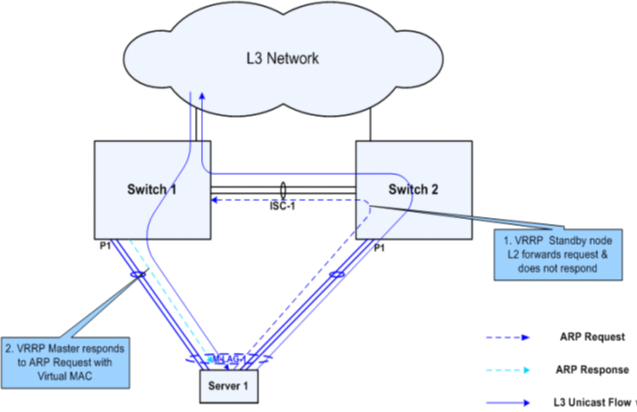
L3 traffic from this point on can be sent on any of the LAG links from the server with the MAC DA set to the VRRP virtual MAC. Since Switch2 never installs the virtual MAC in hardware, it L2 forwards the traffic to Switch1, which takes care of L3 forwarding.
L3 forwarding with MLAG may sometimes result in inefficient use of ISC bandwidth. L3 traffic between two servers connected to the same pair of switches on different MLAG links could end up traversing the ISC link in both directions depending on the hashing algorithm used on the servers.

Consider the topology shown above. Server1 is connected to VLAN “Blue” in network 10.1.1.0/24 and Server2 is connected to VLAN “Red” in network 20.1.1.0/24. Both VLANs have Switch1 as the VRRP master. When the two servers send bidirectional L3 traffic, traffic may get sent over the ISC in both directions depending on how hashing works on the servers.
No comments:
Post a Comment