This article has been written to explain how ipv4 network can be migrate to ipv6 network smoothly based on the case study.
This Case study is based on the case of 6Net backbone which is not related to Extreme Product but it’s good example for Ipv6 network deployment in ISP,
This Case study is based on the case of 6Net backbone which is not related to Extreme Product but it’s good example for Ipv6 network deployment in ISP,
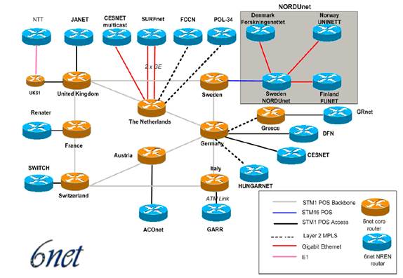
* 6NET is European project to demonstrate that continued growth of the Internet can be met using new IPv6 technology. The project built a native IPv6-based network connecting sixteen countries in order to gain experience of IPv6 deployment and migration from existing IPv4-based networks. This was used to extensively test a variety of new IPv6 services and applications, as well as interoperability with legacy applications.
Network Topology
Deployment Model
Possible Deployment Scenario
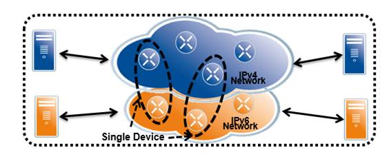
Dual Stack
One of the conceptually easiest ways of introducing IPv6 to a network is called the “dual stack mechanism”, as described in [NG05], which is an update of RFC 2893 [RFC2893]. Using this method a host or a router is equipped with both IPv4 and IPv6 protocol stacks in the operating system (though this may typically be implemented in a hybrid way). Each such node, called an “IPv4/IPv6 node”, is configured with both IPv4 and IPv6 addresses.
- Upgrade Layer 3 devices to IPv6 - do not delete IPv4
- Applications use DNS to choose IP version
- Allows indefinite co-existence
- Enables gradual, app-by-app upgrades to IPv6
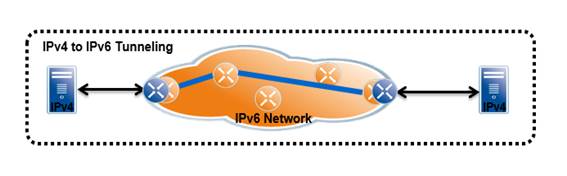
Additional IPv6 Infrastructure (Tunnels)
By additional IPv6 infrastructure we mainly mean tunneling techniques that one can use on top of the present IPv4 infrastructure without having to make any changes to the IPv4 routing or the routers. This method is often used where the complete infrastructure, or parts of it, is not yet capable of offering native IPv6 functionality. Therefore IPv6 traffic has to cross the existing IPv4 network, which is possible with several different tunneling techniques. These techniques are often chosen as a first step to test the new protocol and to start integration of IPv6.
- Tunneling encapsulates one protocol within another
- Commonly referred as 4to6 or 6to4
- Requires dual stack routers
- Manual configuration and difficult to troubleshoot
- IPv6 to IPv4 Tunneling for integrating pockets of IPv6

IPv6-only Networks (Translation)
In IPv6-only networks communication between nodes is just IPv6-only. Communication between a node on the IPv6-only network and a remote node reachable only over IPv4 is not possible, because the hosts can only communicate using IPv6 at the network layer.
- Typically no IPv4 services in this scenario
- IPv4 to IPv6 Tunneling when deploying a new core infrastructure
Extreme Customer’s Case
ISP company in US. Using Dual stack on Core and distribution switches
Core
interface GigabitEthernet1/25
description rtr-servers
ip address xx.xx.xx.xx 255.255.255.252
ip ospf authentication message-digest
ip ospf message-digest-key 1 md5 xxxxxx
ip ospf 1 area 0.0.0.0
ipv6 address xxxx:yyyy:1:13::40:CBB1/64
ipv6 ospf 1 area 0.0.0.0
Distribution
configure vlan core ipaddress xx.xx.xx.xx 255.255.255.252
configure core ipaddress eui64 fe80::/64
configure core ipaddress xxxx:yyyy:1:12::48:cbb1/64
!
configure ospfv3 routerid 0.0.16.16
enable ospfv3
configure ospfv3 add vlan rtr1 instance-id 0 area 0.0.0.0 link-type point-to-point
configure ospfv3 vlan rtr1 bfd on
Ipv6 addressing
Below figure shows IPv6 Global Unicast Address scheme.

6NET Case
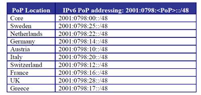
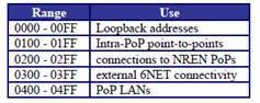
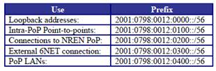
The allocated 6NET address space was ‘2001:0798::/40’. The 6NET available address space ‘2001:0798:0::/40’ was divided into logical sub portions to facilitate future expansions and enable simpler summarization rules when required.
The address range can be seen as:
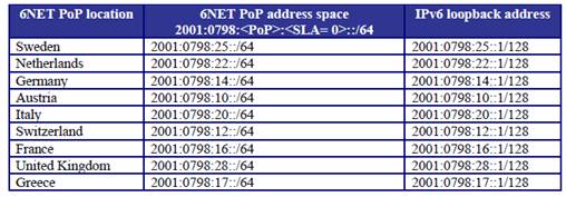
PoP addressing
Using 10 * 48bit sub-netted address from /40 bit mask.
SLA addressing
The SLA (Site Level Aggregate) is used for various prefixes, (mostly) within a PoP.
Switzerland addressing
Loopback address
In networking environments, it is seen as good practice to give each device an IPv6 loopback address. This is an IPv6 address that is not directly assigned to any physical interface and will typically be reachable when the networking appliance (in this case a router) is up and running.
Point-to-Point Links
point-to-point links were numbered from the PoP prefix with a <SLA> = ‘01xx’, where ‘xx’ is a sequence number. This allowed for 256 point-to-point links per PoP with a /64 prefix.
An example of intra-PoP point-to-point prefixes which have a <SLA>=01xx for the Germany PoP with <PoP>=14 would be:
2001:0798:0014:0100::/64
2001:0798:0014:0101::/64
2001:0798:0014:0102::/64
2001:0798:0014:0103::/64
Router Naming Convention
The Router name was comprised of the ‘domain name’, the ‘PoP name’ and a sequential ordinal number. The equipment ordinal numbers started with 6. The possible extra routers would be called uk61, uk62 and so on.
Example: The 6NET core router in the United Kingdom: <uk6.uk.6net.org>
SURFnet Case
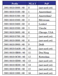
SURFnet received an official IPv6 prefix from the RIPE NCC in August 1999 of length /35, which was enlarged to a /32 during the summer of 2002. 2001:0610::/32

PoP addressing
Using 17 * 40bit mask prefix from 35 bit mask address.
Routing – Case#1 ( 6Net )
IGP - ISIS
Routing Diagram
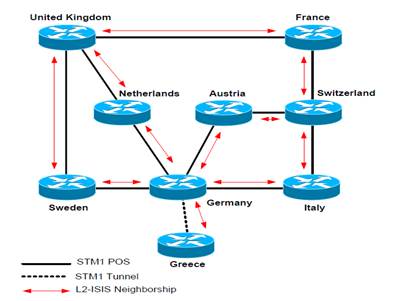
The options available for an IGP routing protocol within 6NET were: static routing, RIPv6 or IS-IS. The option ‘static routing’ would have been very difficult to manage in practice, and would not have been very scalable. The dynamic routing options available were ‘RIPv6’ and ‘IS-IS’.
RIPv6 is a distance vector routing protocol while ‘IS-IS’ is a link-state protocol. Although a distance vector routing protocol is easier to troubleshoot and the operation simpler to understand, it was preferred to utilize a link-state protocol due to its advantages in convergence, tuning and additional features (like opaque information, enhanced TLV (Type/Length, Value) information for Traffic Engineering, etc.).
Integrated IS-IS was used only to distribute the core router reachability. For everything else BGP4+
was used. No route exchange was used between IGP and EGP.
IS-IS structure
The hierarchical structure of ISIS used to utilize two different levels of routing, this allow routing protocol to scale through summarization. The 6NET Core backbone initially consisted of a relatively small amount of routers and prefixes. Therefore, within 6NET a pure Level-2 routing domain was implemented with single area.
IS-IS interface metric
In order for a routing protocol to decide the best path from a one network to another it is important to assign a cost or metric to each interface. Typically, the metric is a direct correlation between value and the speed of the link. Other correlation can be delay, reliability, etc. Primarily, the link speed was used for the 6NET core according to the following table:

Passive Interface
When a router interface is placed in the routing process it will send out IS-IS Hello packets in order to form an IS-IS neighbor with peering IS-IS routers over that interface. There are instances where it is desirable to include an interface in the IS-IS routing process to distribute the IPv6 prefix among the Level-2 area, but to never form an adjacency over that interface. To disable the sending of IIH packets the interface can be made passive with the command <passive-interface> under the IS-IS routing process. It is recommended to do this on stub LAN network interfaces. In 6NET, all loopback interfaces and interfaces connecting to the NREN PoP routers and LAN stub interfaces were made passive.
CLNS Address
The 6NET Core consisted of 9 routers that formed the International-backbone. The following CLNS addresses were placed on the 9 routers:

IPv6 BGP
Routing Diagram
BGP4+ was used between 6NET core and participant NRENs, 6NET and other organizations. Each
NREN used their AS numbers. The 6NET core had a separate AS number.

Routing Policy
Neighbors with the same update policies can be grouped into peer groups to simplify configuration
and to make updating more efficient.
Two initial peer groups were defined:
- Peer group for peerings between 6NET core PoP and NREN PoP: 6NET_EXTERNAL_NREN_PEER
- Peer group for peerings between 6NET core PoPs: 6NET_INTERNAL_6NET_PEER
iBGP
- No Route-reflector was used due to the relatively small number of core routers.
- Instead, full mesh BGP peering was configured inside the core.
- BGP peering were secured with TCP MD5 authentication from the beginning to prevent the wrong peering by accident.
- The external peers were grouped together to have same routing policy with the group name:6NET_EXTERNAL_NREN_PEER.
Routing – case#2
IGP – OSPFv3
using OSPFv3 inside of their network. OSPFv3 is only for distribution of BGP next-hop information.
Structure
Core and Distribution switch only have area 0.0.0.0. Customer’s network can be covered by ospf backbone area, because IGP only deliver the information BGP next-hop. Switch only have 148 OSPFv3 ipv6 intra route.
interface TenGigabitEthernet3/4
ip address x.x.x.x 255.255.255.252
ip ospf authentication message-digest
ip ospf message-digest-key 1 md5 xxxxx
ip ospf network point-to-point
ip ospf bfd
ip ospf 1 area 0.0.0.0
ip ospf cost 25
history BPS all
ipv6 address xxxx:yyyy:1:20::40:CBB1/64
ipv6 ospf 1 area 0.0.0.0
ipv6 ospf cost 25
ipv6 ospf bfd
bfd template slow
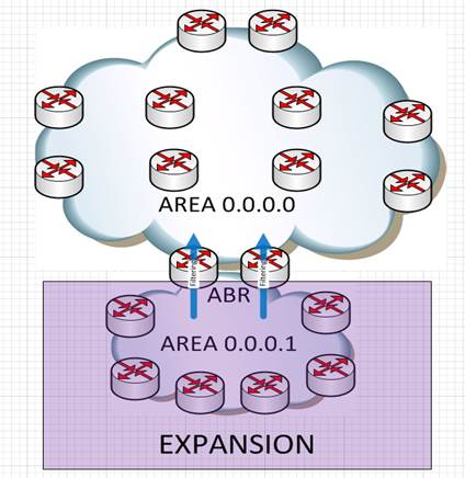
Expansion
But if customer’s network expand and cannot be covered by one area, then it can be expand by using OSPF normal area, and filtering of IGP network can be accomplished by using policy on ABR router.
OSPFv3 BFD
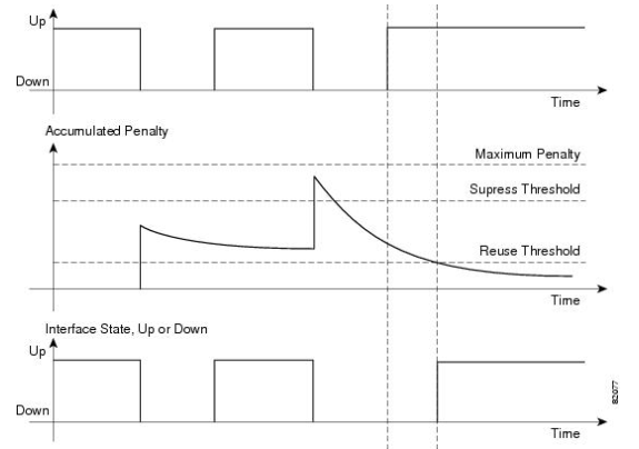
For fast routing convergence, customer is using OSPFv3 BFD on the cisco Core router. Also using Dampening feature to maintain stable routing information by suppressing the effects of excessive interface flapping events on routing protocols and routing tables in the network.
[Core Router]
interface Port-channel1.123
ip policy route-map NAT
ip ospf authentication message-digest
ip ospf message-digest-key 1 md5 xxx
ip ospf bfd
ip ospf cost 353
ipv6 ospf cost 353
ipv6 ospf bfd
bfd template slow
bfd-template single-hop slow
interval min-tx 999 min-rx 999 multiplier 3
dampening 3 1500 3000 5
In this example, the half life to 3 seconds, the reuse threshold to 1500, the suppress threshold to 3000; and the maximum suppress time to 5 seconds:
Distribution switch
Below example is from the ISP where didn’t deploy IPv6 yet.
enable bfd vlan "vlan_name"
configure bfd vlan "vlan_name" receive-interval 100 transmit-interval 100
configure ospf vlan "vlan_name" bfd on
IPv6 BGP
Route reflector
Full mesh between bgp router inside of AS is not possible because of many BGP routers inside of AS, so Core Router configured as Route reflector.
Core Router
router bgp xxxxx
template peer-policy ibgp-base
route-reflector-client
send-community both
exit-peer-policy
!
template peer-policy ibgp6
route-map IBGP-IN-IPV6 in
route-map IBGP-OUT-IPV6 out
default-originate route-map IBGP-DEFAULT-ORIG-IPV6
inherit peer-policy ibgp-base 10
exit-peer-policy
!
address-family ipv6
redistribute connected route-map IBGP-REDIST-IPV6
neighbor xxxx:yyyy:0:1038::CBB1 activate
neighbor xxxx:yyyy:0:1038::CBB1 inherit peer-policy ibgp6
Distribution Switch
create bgp neighbor xxxx:yyyy:0:40::cbb1 remote-AS-number xxxxx
configure bgp neighbor xxxx:yyyy:0:40::cbb1 source-interface ipaddress xxxx:yyyy:0:48::cbb1
configure bgp neighbor xxxx:yyyy:0:40::cbb1 password encrypted "xxxxxx"
configure bgp neighbor xxxx:yyyy:0:40::cbb1 description "core.gp1"
configure bgp neighbor xxxx:yyyy:0:40::cbb1 peer-group reflectors6 acquire-all
enable bgp neighbor xxxx:yyyy:0:40::cbb1
peer group
Distribution switch has two peer group. Peer group peergroup6 is for the neighbor from private AS, and peer-group reflectors6 is for core switches which is route-reflector. By using Peer group make configuration simple and modular.
configure bgp peer-group peergroup6 address-family ipv6-unicast send-community both
configure bgp peer-group peergroup6 address-family ipv6-unicast route-policy in ebgp-ipv6-in
configure bgp peer-group peergroup6 address-family ipv6-unicast route-policy out ebgp-ipv6-out
enable bgp peer-group peergroup6 capability ipv6-unicast
enable bgp peer-group peergroup6 address-family ipv6-unicast originate-default policy ebgp-orig-dflt-ipv6
configure bgp peer-group reflectors6 address-family ipv6-unicast send-community both
configure bgp peer-group reflectors6 address-family ipv6-unicast route-policy in ibgp-only-inout
configure bgp peer-group reflectors6 address-family ipv6-unicast route-policy out ibgp-only-inout
enable bgp peer-group reflectors6 capability ipv6-unicast
enable bgp peer-group reflectors6 address-family ipv6-unicast soft-in-reset
using pre-defined peer group to bgp neighbor.
configure bgp neighbor xxxx:yyyy:0:20::cbb1 peer-group reflectors6 acquire-all
graceful restart
To protect data path during control plane restart, graceful restart enabled on cisco router.
bgp router-id x.x.x.x
bgp log-neighbor-changes
bgp graceful-restart restart-time 120
bgp graceful-restart stalepath-time 360
bgp graceful-restart
Redistribute
Static route and directly connected interface redistributed to BGP. No redistribution between OSPFv3 and BGP. By using export policy, only certain NLRI can be re-distributed and set community value and make next-hop self.
Great Posting!
ReplyDelete